Here is a description of a regenerative receiver. Its design is based
on the principles outlined in another Paper. It is made with components
manufactured in 2019. The results are up to the task: it is possible to
realize real SSB QSOs with America on 15 m.
The design is based on the following 6 principles:
- Use of a low L/C ratio (high tuning capacity, at least 470 pF). This
improves the frequency stability and decreases the synchronization
phenomenon and the hand effect.
- Use of an adjustable RF attenuator at the receiver input. This reduces the risk of receiving powerful out-of-band stations.
- Use of a buffer stage between the antenna attenuator and the feedback
stage. This is essential to avoid the risk of background noise when
tuning in (tunable hum) and to reduce the frequency variations that
occur when adjusting the RF attenuator.
- Decoupling of the diodes from the power supply circuit by 10 nF capacitors to eliminate the same noise.
- Low impedance for the 50 Hz between the detector input and ground
e.g. by using a high link capacitance (100 nF). This eliminates the
background noise induced by the capacitive coupling with the 50 Hz
mains.
- Use of an AF amplifier with high gain and low noise in order to obtain a satisfactory output power.
In addition, the coils and capacitors of the tuning circuit must be of
excellent quality. We have chosen to build this receiver with bipolar
transistors which have the advantage of being relatively solid,
inexpensive and easy to control with an ohmmeter.
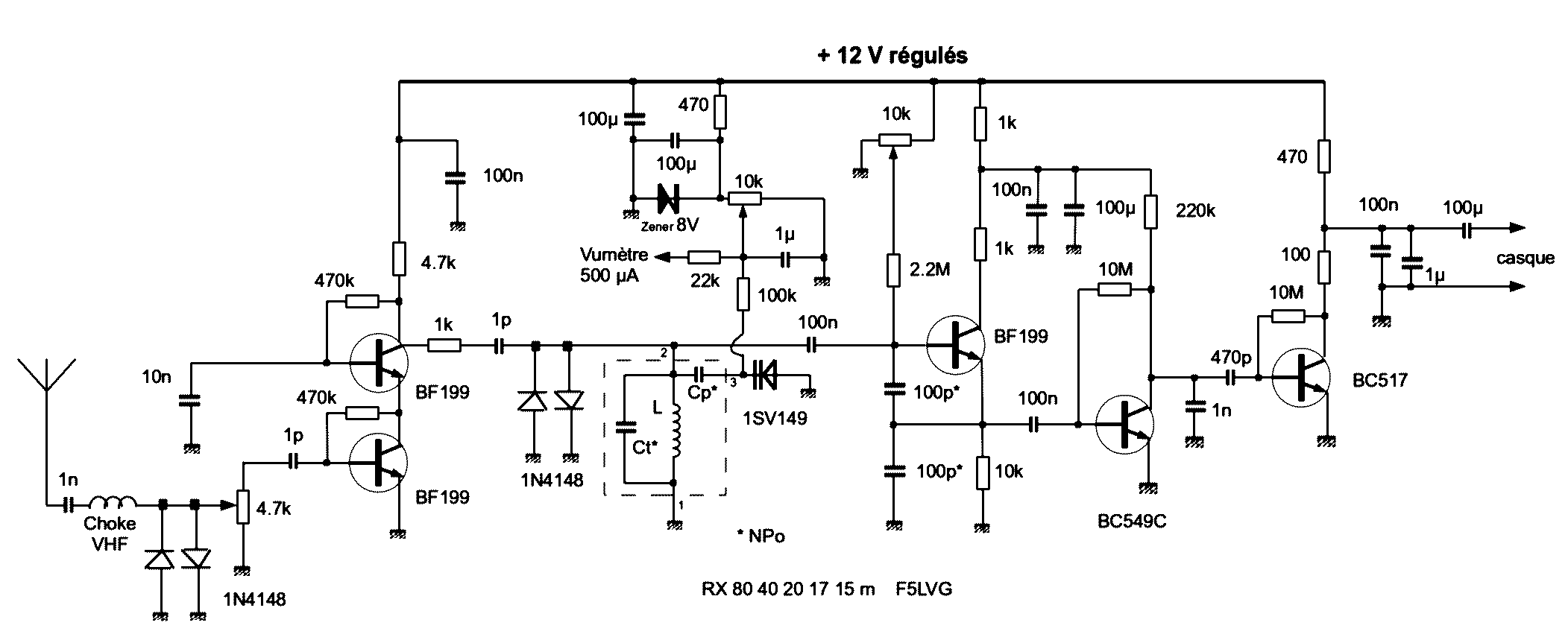
Let's study the theoretical scheme by dividing it into 3 stages: RF, regenerative detector, AF.
Let's start with the antenna input.
A VHF choke coil prevents powerful FM stations from entering the
receiver. Two 1N4148 diodes are used to protect the first transistor if
the receiver is used close to a transmitter. The buffer stage consists
of 2 transistors in cascode circuit, which allows an excellent
independence between input and output. Note the very low coupling capacitors at the input and output. They avoid saturation of
the RF stage and the detector. The 1 kohm
resistor is used to avoid VHF or UHF oscillations.
The regenerative detector includes 2 transistors.
Two new diodes 1N4148 are used to protect the following transistors. The resonant circuit is composed of 3
interchangeable elements for each band: the coil, a high value parallel
capacitor and a capacitor in series with a high capacitance varicap
diode (480 pF). This series capacitor spreads each band to the
maximum. This resonant circuit is coupled by a 100 nF capacitor to a
first transistor mounted in Colpitts to obtain the feedback. This is
the role of the 2 x 100 pF capacitors which thus add 50 pF to the
tuning capacitance. The 1 kohm resistor in the collector circuit is
used as before to avoid VHF or UHF oscillations. The feedback is
adjusted by changing the base voltage with a 10 kohm potentiometer. The
frequency is adjusted by varying the voltage applied to the varicap
with an identical potentiometer. These two potentiometers must be 10
turns. A 500 µA (or less) meter in series with an adequate resistor
(approximately 22 kohm) makes a simple frequency dial. The
detection is done by a second transistor crossed by a very low current,
which is easily obtained with a 220 kohm collector resistance. The 1 nF
capacitor allows RF filtering.
The last stage corresponds to the low frequency amplifier.
It is a Darlington which allows a very high input impedance, well
adapted to the high impedance output of the detector. The 100 ohm
resistor and the 100 nF and 1 µF capacitors prevent self-oscillations
of the stage. The gain is sufficient for good headphone listening.
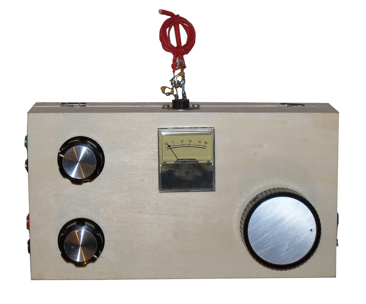
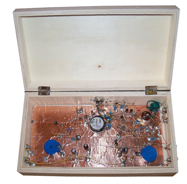
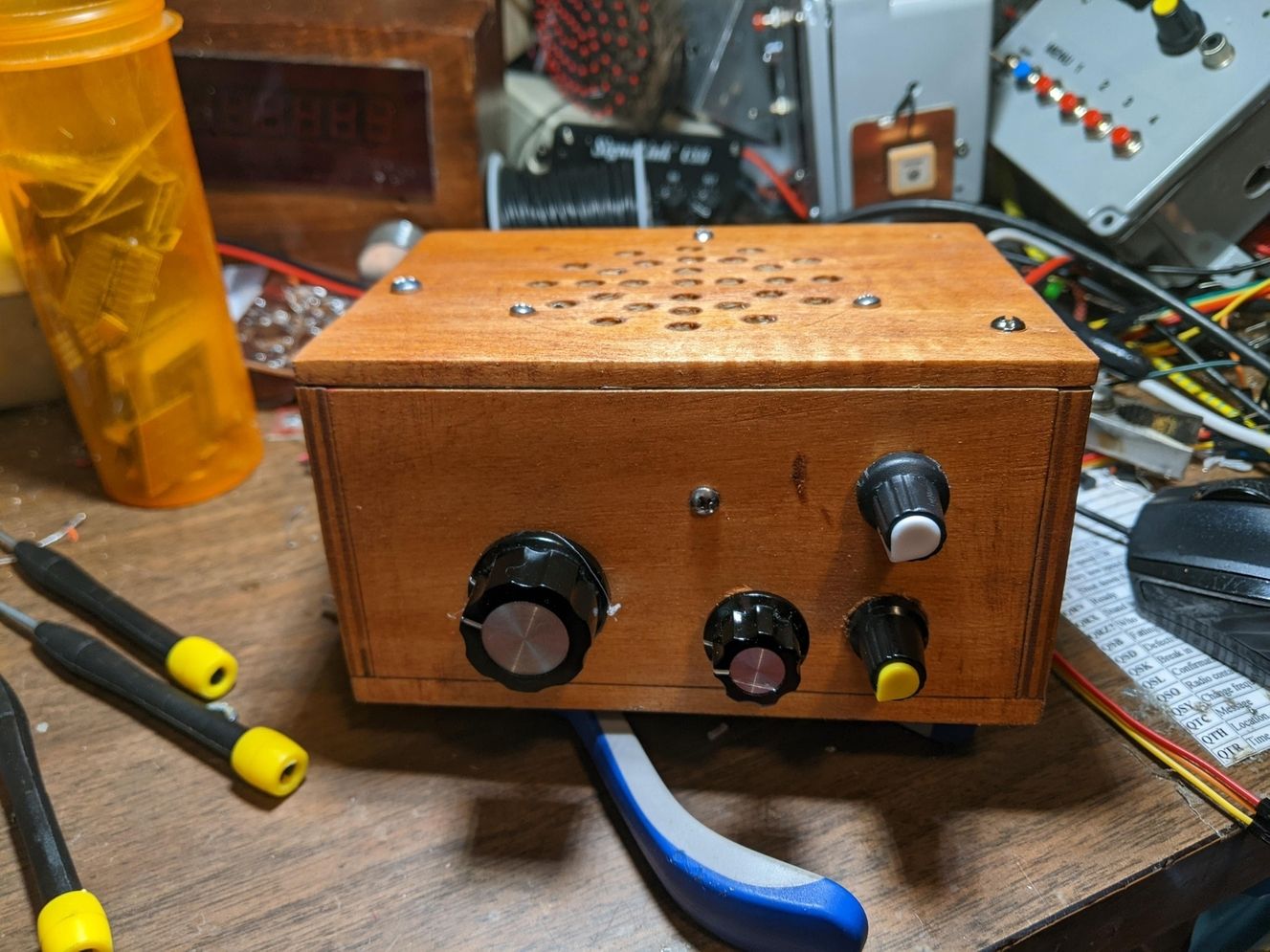
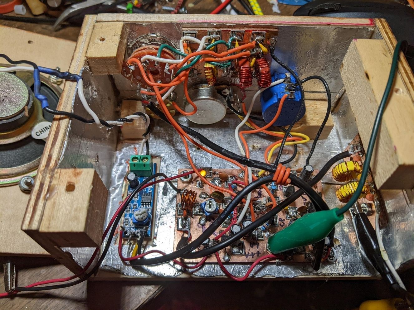
Let's go to the practical realization.
The receiver is built in a wooden box of 12x22x2.5 cm. Adhesive copper
foils (5 cm) are glued on the back of the front panel. These bands
serve as shielding and ground plane. It is useful to make soldering
points between the different strips. Resistors of 10 Mohm 0.25W are
used as connection points. Their high value equates them to resistors
of infinite value. The power and antenna sockets are on the left side,
the headphone sockets on the right side. The coils with the Cp and Ct
capacitors are fixed on 3 or 4 pin DIN plugs which are thus easily
interchangeable. All capacitors marked with a star must be NPO
multilayer ceramic capacitors. Only these have sufficient stability for
satisfactory frequency stability. The connections between the DIN
socket, the varicap, the 100 nF capacitor, the 100 pF capacitor and the
transistor of the regenerative stage must be very short.
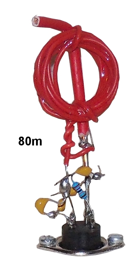
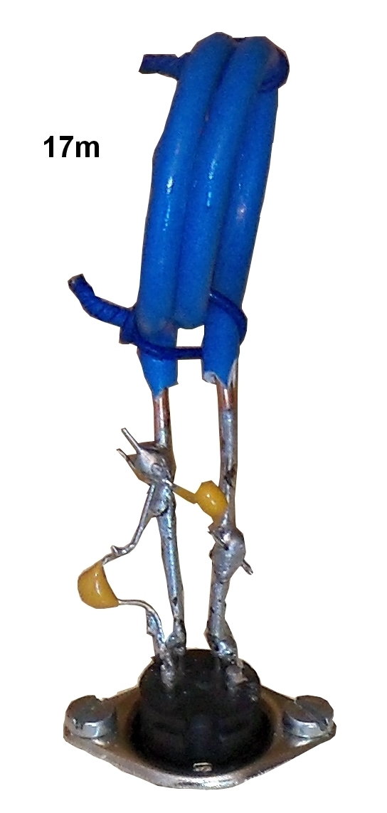
Let's start with the construction of the plugin coils. In fact, these
are the L coil and the Ct and Cp capacitors. The simplest support is a
DIN plug with only the socket with the pins. In this assembly 3-pin DIN
plugs can be used. However, the purchase of a set of 4-pin plugs will
allow more flexibility for other assemblies in the future.
The Ct and Ct capacitors are multilayer ceramics of the NPO type. In a
simple way, Ct determines with and the 2 x 100 pF capacitors the
maximum frequency that will be received. Ct in series with the varicap
determines the bandwidth that will be received. There is no
adjustable capacitor, which would make the task easier. Indeed, good
adjustable capacitors are expensive and hard to find. It is therefore
necessary to look empirically for the adequate value by putting 2 or 3
capacitors in parallel. Start with a high value capacitor, then
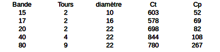
approach an adequate value with smaller capacitors. For example, I
needed 578 pF for Ct for the 17 m. These 578 pF are constituted by 3
capacitors of 470 100 and 8 pF.
The coils consist of 40 m and 80 m of PVC insulated single wire (YV
cable) with an outer diameter of the cable of 1.1 mm and 0.5 mm for the
copper wire (section 0.2 mm²). These coils are fixed 2 small twisted
wires on a 20A electric wire welded to the ground pin (1) of the DIN
socket. This wire is 9 cm long, the bottom 4 cm are stripped and the
top is folded back by 1 cm. One wire from the coil is soldered to the
stripped part of the 20A wire, the other to pin 2 having stripped the
wire by 4 cm. The Ct capacitors are soldered between the wire going to
pin 2 and the 20A wire. The Cp capacitors between the wire going to pin
2 and pin 3.
For the 15 m, 17 m, and 20 m the coils are made of 20A installation
wire (2.5 mm² section). Two small twisted wires ensure its rigidity.
The legs measure approximately 4 cm, are stripped and soldered to pins 1
and 2. The capacitors Ct are soldered between the leads to pins 1 and
2. Cp capacitors between the tab going to pin 2 and pin 3.
For the diameter, the templates were a felt pen (10 mm), a marker (16
mm) and a noval lamp (22 mm). It is almost certain that you will have
to use other Ct and Cp values.
To fine-tune the frequency range, you apply the maximum voltage
to the varicap and set the receiver to oscillate. There are two
possibilities here. Either you look for the frequency on a receiver in
SSB position, with a few centimeters of antenna and choosing the widest
possible selectivity, or you use a well-calibrated HF generator. When
everything is right, you glue the coil turns with cyanolite (superglue).
To be used with a transmitter, it is essential to have an antenna
switch controlled by the transmitter and a switch in the headphone
circuit.
What are the results with receivers? It is possible to listen for more
than 15 minutes to an SSB station without changing the tuning, even on
21 MHz. The noise level of a 2x10m antenna is always higher than
the background noise of the receiver. For several weeks, I used only
this receiver and performed SSB QSOs on 15m, 17m, 40m, and 80m. There
was no QSO over 20m, my home-made transmitter did not cover this band.
Successful QSOs with North America on 15 m or 17 m is a measure of this
receiver's performance.
Olivier Ernst
F5LVG
PS Keywords to find certain components on Ebay :
- NPO multilayer ceramic capacitors : NPO multilayer kit
- Assortment of ceramic capacitors from 1pF to 100nF: ceramic capacitor kit 1pf 1000pcs
- DIN male plugs (be careful not to take mini DINs): din male plug 4 pin 10pcs
- DIN female sockets: din female socket 4 pin 10pcs panel
- Potentiometers 10k 10 turns (I advise to use more than 2
potentiometers, false contacts being very frequent) : potentiometer 10k
10 turns wirewound 5pcs