Regenerative receiver 5.5 to 18 MHz
And 2 variants: 3 to 4 MHz and 5.5 to 18 MHz or 40m and 80m ham bands only
F5LVG
Olivier Ernst
Until the late '50s, most ham radio receiver built regenerative receivers before superheterodyn. Indeed, this type of receiver needed only one or two tuned circuits and was able to demodulate amplitude modulation as well as telegraphy with good sensitivity.
This type of receiver almost completely disappeared in the transition from tubes to semiconductors.
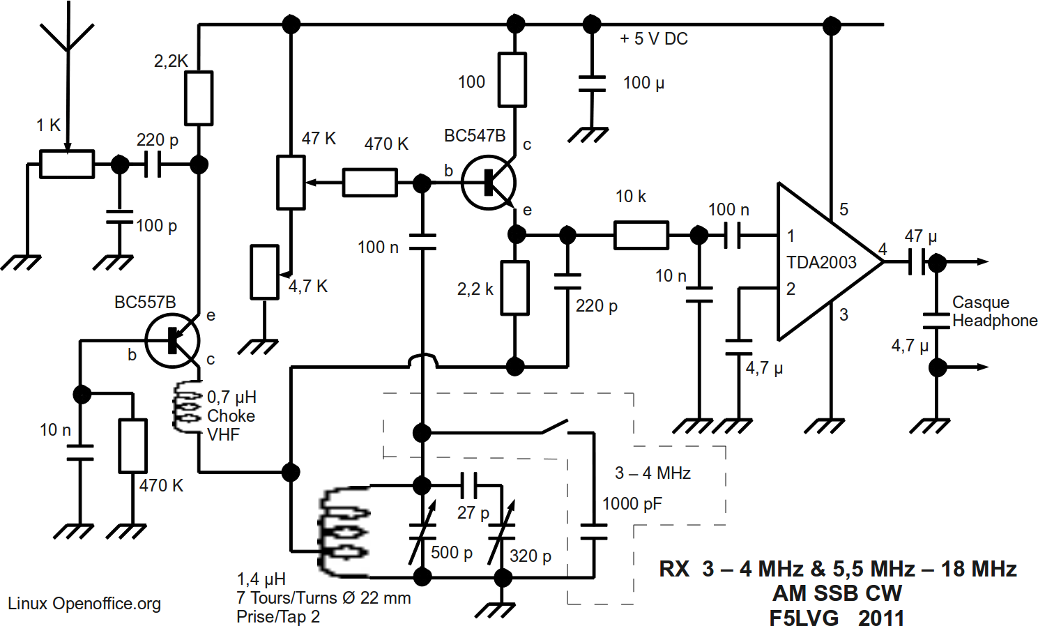
The receiver described below is designed to be built by a beginner. It uses rugged components. It requires no switching. A single tuned circuit must be realized. Its frequency range is 5.5 to 18 MHz. It is possible to receive the main broadcast bands and ham bands of 20 m and 40 m. It demodulates AM SSB and telegraphy. The reception in France of American amateur stations transmitting in SSB on 20 and 40 m is possible with an external antenna.
The principle of a regenerative receiver is simple. The selectivity is due to a single tank circuit (a coil and a variable capacitor) tuned to the frequency to be received. To obtain a good selectivity and a good sensitivity, the resonant circuit must have a low RF resistance. It is possible to decrease the RF resistance circuit by connecting it to an amplifier and by a feedback loop. If the feedback corresponds exactly to the losses in the resonant circuit there no loss and the selectivity and the sensitivity are maximum. If the feedback is greater than the losses, the circuit begins to oscillate. Conversely, if the signal back to the input is too low, the sensitivity and the selectivity decrease.
Our resonant circuit will be connected to the input of a transistor (its base). For the output of the transistor, we use its emitter because the output signal is in phase with the input signal. The emitter of transistor will be connected to the resonant circuit, at an intermediate tap of the coil. By varying the voltage applied to the base of the transistor, we can adjust its gain and thus the value of the signal reapplied to the resonant circuit. The point where the transistor goes into oscillation is called the oscillation threshold. Just after this point, the oscillation will interfere with the waves received by the receiver. This will decode the CW and demodulate the SSB. To demodulate the amplitude modulation, the feedback must be held just before the oscillation threshold to avoid ringing by interferences. The transistor, due to its nonlinear characteristic, allows the detection of signals and thus demodulation of SSB, AM, and CW.
At the transistor output, the signals are extremely weak. Therefore, it should be followed by a high gain AF amplifier. An integrated circuit is well suited for this task.
The antenna coupling to tank circuit is critical because of three problems. Firstly, the more the antenna is coupled to the resonant circuit, the more it is damped, and the receiver unselective. Sometimes its become impossible to obtain the oscillation threshold (dead spot). Secondly, if the receiver is not perfectly grounded, the motions of the operator can change the characteristics of the antenna and therefore the characteristics of the resonant circuit. When the operator moves his hands the frequency changes: This is the hand effect or the body capacity. It becomes impossible to listen SSB correctly. Thirdly, a 50 Hz (or 60 Hz) hum can occur. When oscillating, the detector stage becomes a transmitter connected to an antenna. This RF signal can be received by the AC lines. From there, it reaches the rectifier diodes of the power supply. These diodes become an amplitude modulator that modulates the RF signal with the 50 Hz signal. This modulated RF signal comes back to the receiver by the power supply connection. Therefore, we receive this powerful modulated wave which covers all other stations. This is the so called tunable hum. This hum exists only above the oscillation threshold. No hum is perceptible below this threshold. To avoid this hum, the antenna doesn't be connected directly to the resonant circuit. The solution of these 3 problems is a buffer stage between the antenna and the detector. The simplest is to use an aperiodic amplifier (untuned amplifier) in common base. Furthermore, all rectifier diodes must be shunted by a small by-pass capacitor (10 nF) to avoid the modulation effect that induces the tunable hum.
The diagram of the receiver is easy to understand. The antenna is connected to a 1kohm potentiometer to avoid saturation. The BC557B transistor is an aperiodic RF amplifier. The 100 pf capacitor and VHF choke eliminate any FM stations. The output of this transistor is applied to an intermediate tap of the coil. The tuned circuit is connected by a 100 nF capacitor to a BC547B transistor which is the regenerative detector. Transistors do not detect as vacuum tube. It is important that the coupling capacitor has a very low impedance in RF as well as AF in transistors while this capacitor must have a low RF impedance and a high AF impedance for vacuum tubes. The two potentiometers (4.7 kOhm and 47 kOhm ) are used to adjust the gain of that stage (regeneration control). The output of the transistor is the emitter. The output signal is applied to the tuned circuit for regeneration and, via a low pass filter, to an AF amplifier. This AF amplifier consists of a single integrated circuit TDA2003. It allows a powerful listening through headphones. The power supply is 5 V, but not critical (4.5 to 6 V). For easy tuning and regeneration control a system of vernier is used for the tuning capacitor and the regeneration potentiometer.
Almost all components are easy available. Only the variable capacitors are difficult to find. They must be multiturn air variable capacitors. The easiest way to find them is ebay with the 3 keywords: “air variable capacitor”. I use two variable capacitors, each with 2 cages 370 and 320 pF. To cover the frequency range from 5.5 to 18 MHz, the total value of the variable capacitor should be 500 pF or more. A vernier is obtained with a 27-pF capacitor in series with one cage of the second variable capacitor. This 27-pF capacitor should have a high temperature stability. So use a NPO, styroflex or silver mica capacitor.
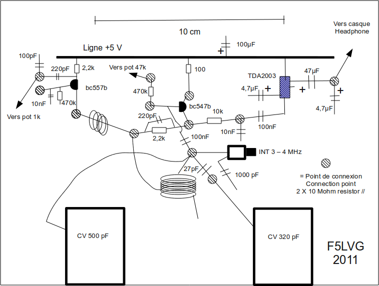
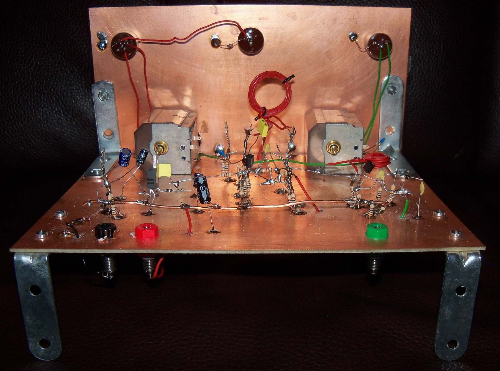
The receiver is built on two copper clad board measuring 15 x 20 cm. The first plate is horizontal, copper up. The second plate serves as the front, the copper surface is oriented backwards. A tip for low-cost connection points : just use 1 or 2 resistors of 10 Mohm. These resistors are completely negligible. It's almost an infinite resistance! The connection between the tuning coil and the variable capacitor of 500 pF should be as short as possible. The two variable capacitors are required to be attached to the horizontal plate and not on the front.
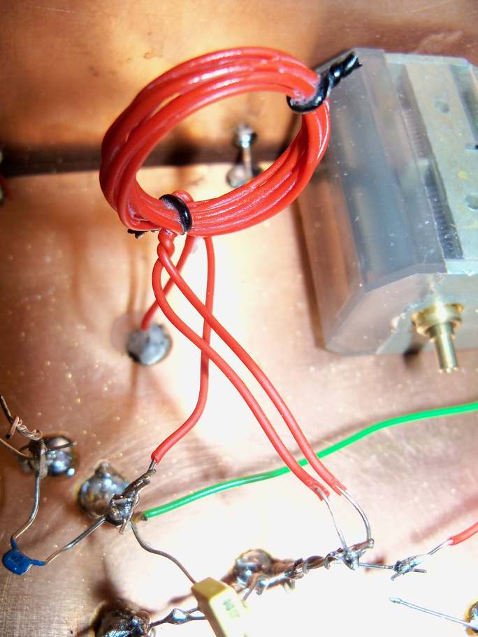
The tuned coil is made with an electric wire : PVC insulation, outer diameter 1.1 mm, conductor diameter 0.5 mm and section 0.2 mm ². I made the coil on a 22 mm diameter cylinder. It was an old noval electronic tube. The coil has 7 turns, which corresponds to 1.4 uH, with an intermediate tap at 2 turns. Remove the coil from the tube. To improve the rigidity of the coil, when the receiver is finished, apply some glue on it. The absence of a coil former, the absence of switching system and the use of a large diameter wire allow low losses and therefore an outstanding performance of the receiver.
The VHF choke has 10 turns on a diameter of 8 mm. This coil is not critical. Its value is 0.7 µH.
For the variable capacitors, it is important to use buttons with at least 3 cm in diameter. To make a rudimentary dial , use 3 cm screw for the button.
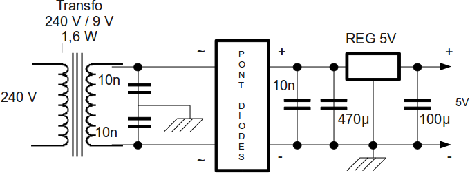
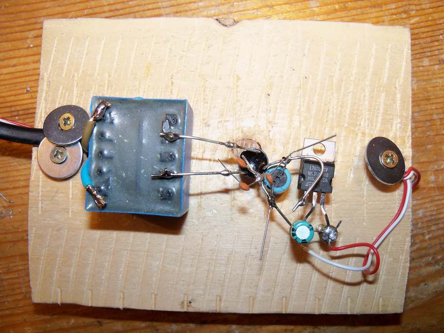
The receiver uses a 5 Vdc power supply. Don't forget the 10 nF capacitors between the diode bridge and the ground to avoid the common hum.
To try the receiver, connect the antenna, turn the variable capacitor of 500 pF to halfway, put the headphones and turn the potentiometer 47 kohm for 0 V to 5 V. At some point, you should hear a plop and an increase in background noise. It indicates that the receiver works. Plop noise corresponds to the oscillation threshold. Then turn the variable capacitor of 500 pF and , you will hear many whistles. Amplitude modulation is listen just below the oscillation threshold, SSB and telegraphy over it. Note that the adjustment of the regeneration varies the tuning frequency.
Once the receiver works, proceed to the frequency calibration. As shown in the photograph, the dial is made for the variable capacitor of 500 pF. It is simply plotting 8 diameters. The end of each diameter is indicated by a letter. Then make a table of correspondence between the frequencies and the letters. Because of the reduction gear, I suggest to differentiate the turns on the table. To accurately calibrate the frequencies, it is necessary to have, a receiver with digital display. Turn the regeneration potentiometer to the maximum. The vernier capacitor must remain throughout the procedure at its maximum capacity. Then, it remains to seek the position of the variable capacitor of 500 pF giving a ringing in the digital receiver. At zero beat, your receiver is set exactly on the same frequency as the digital receiver, except harmonic problem. Personally, I made a very simple table, giving only the MHz.
Now you have a small receiver that gives spectacular results for both shortwave broadcasting, for the amateur bands 20 and 40 m.
Problem of synchronization.
When an external signal is applied to an oscillator, the frequency of the oscillator tends to be synchronized to the frequency of the external signal. This phenomenon is more important if the difference in frequency is low, the external signal strong, and the C/L value low.
For CW and SSB, when the signal strength increases the pitch decreases and in some cases the external signal pulls the pitch to zero beat : the receiver blokes. To resolve this problem there are 3 solutions : first decrease the antenna coupling, second increase the power of the oscillator, third use a very high C for the resonant circuit. That explain why SSB is difficult to demodulate on 14 mhz, because of a low C/L ratio.
80 m Variant
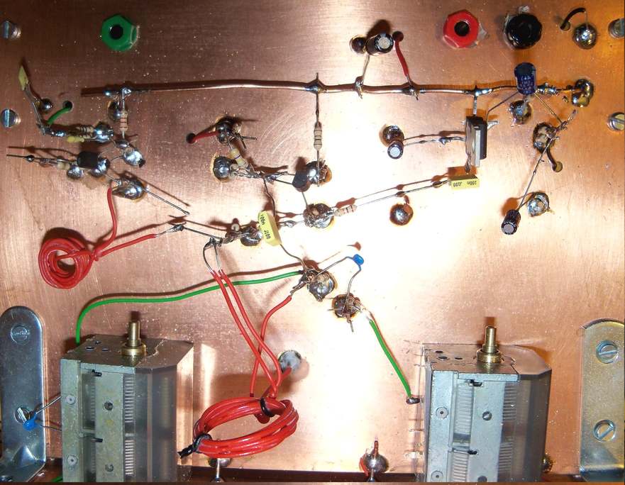
Note that it is possible to receive the 80 m band by adding a parallel capacitor of 1000 pF. This capacitor must be of the NPO, styroflex or silver mica. Put a small switch to select it or not. Its wiring must be extremely short. A photograph shows the practical realization. The fact that the same resonant circuit can oscillate from 3 to 18 shows its quality.

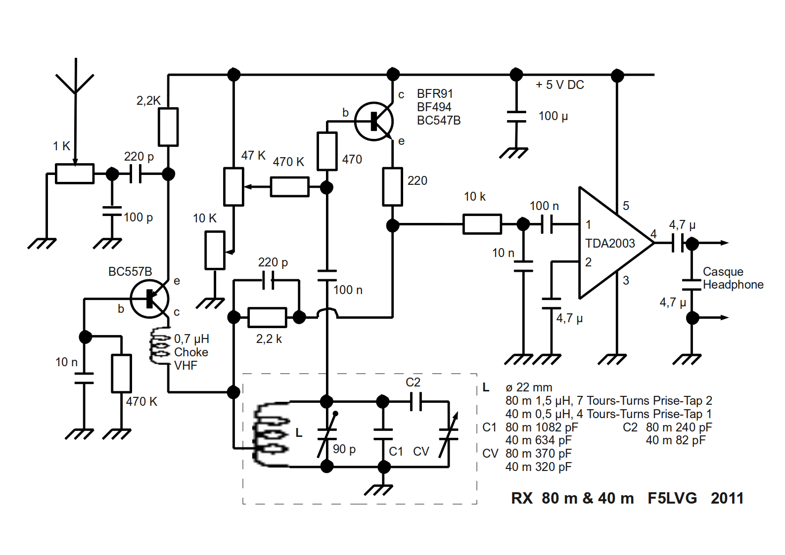
40 m and 80 m Variant
This is a version provided exclusively for amateur radio can receive 40 to 80 m. For each band, there is a complete resonant circuit with a very high C to avoid the synchronisation effect. A miniature DPDT switch select the band. You must use silver mica or air capacitor for the tuned circuit. There is a single air variable capacitor with 2 cages (one cage for each band).
The transistor for the detector is not critical. However, the more its transition frequency, the lower detuning during the feedback control. So I use a transistor (BFR91A ) with a high Ft (5000 MHz!). The emitter resistor decreases detuning too.
I did many SSB QSO on 40 and 80 m with this receiver and a homemade transmitter. In that case, a standby switch in necessary. This is a DPDT miniature switch that disconnects the antenna and the headphone connections during the transmission.
Good DX F5LVG