REGENERATIVE RECEIVER THEORY
In 1912, the available triode tubes only allowed very low amplification. Edwin Howard Armstrong (1890-1954) in empirical tests suddenly obtained considerable amplification. He had just discovered the phenomenon of feedback: by reapplying part of the output signal to the input of an amplifier, the total amplification is considerably increased.
This considerable gain, combined with an increase in selectivity, led to a major development of radio in the 1920s, before being gradually replaced by superheterodyne technology in the 1930s.
The extraordinary results of the feedback explain that some amateur radio amateurs still use this technique to make simple receivers, but allowing receiving stations from America or Oceania sometimes with 3 or 4 transistors.
1 Amplification
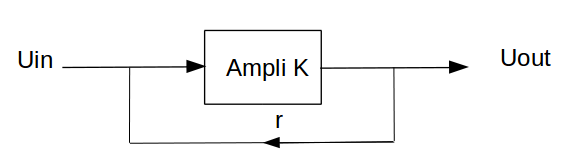
Let be a gain amplifier stage K in the absence of feedback. Let's reapply to the input a percentage r of the output voltage.
K ( Uin + r Uout) = Uout => K Uin = Uout - K r Uout =>
K Uin = Uout ( 1 - K r) => K / ( 1 - K r) = Uout / Uin
The gain Gr with feedback corresponds to the ratio Uout / Uin therefore Gr = K / ( 1 - K r)
Let's take an example. Let's say an amplifier with a gain of 10. Let's apply a feedback of 0.095 (9.5%). The gain increases to 200! Let's increase the feedback even further by applying 10%. The gain becomes infinite, i.e. the circuit oscillates.
The feedback thus considerably increases the gain of an amplifier. The limit is reached when the amplifier starts to oscillate.
2 Selectivity
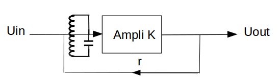
Let's add a resonant circuit to the amplifier input. Without feedback, the selectivity is that of its impedance curve. For example, if at a frequency F1 the impedance Z of the circuit is half that of the resonance frequency Fo, the frequency signal F1 is attenuated by 2 at the output of the resonant circuit with respect to a frequency signal Fo. The relative attenuation persists at the amplifier output.
Let's add the feedback. The percentage r of the output reapplied to the input will also vary according to frequency. This explains the increase in selectivity.
Let us take again our example: that of a gain stage k = 10 without feedback and a value of r at resonance Fo of 9.5%. Let be two stations, the desired one of frequency Fo on which the receiver is set, and a second station of frequency F1 for which the resonant circuit gives the attenuation of 2 (-6dB) without any feedback. With the feedback, the gain becomes 200 for the Fo frequency. On the other hand, the feeback is only 4.75% for F1. The gain therefore becomes equal to 19. The feedback therefore provided a relative attenuation of the frequency F1 compared to Fo of 200/19 or 10.5 (-20db).
This gain in selectivity should be understood as follows: the more the feedback is increased, the greater the amplification difference between Fo and F1. The most important selectivity is therefore obtained in the immediate vicinity of the oscillation.
This mechanism explains a major defect in the regenerative receivers: if station F1 is already received without feedback, the application of the feedback will not eliminate it. It will even be received more and more loudly by increasing the feedback.
The only way to mitigate this problem is to attenuate the signals at the receiver input so that no stations are received without feedback. Only the extra gain provided by the feedback will allow the different stations to be received.
To obtain good selectivity, any regenerative receiver connected to an "effective" antenna must therefore be preceded by a variable RF attenuator.
If one station is really much stronger than the others, as is sometimes the case with broadcasting stations close to amateur bands, it will sometimes be almost impossible to eliminate it completely. On a well-designed receiver, this must remain exceptional.
3 Reception of telegraphy and SSB
The simplest demodulator is a detector. It is directly effective for amplitude modulation (AM). If the oscillation threshold is exceeded, the resulting wave interferes with the carrier and gives a hissing sound whose frequency is equal to the frequency difference between the oscillation wave and the transmitter carrier (AM). For the reception of the amplitude modulation, it is therefore necessary to adjust the feedback just before the oscillation threshold. On the contrary, for single sideband (SSB) demodulation, the oscillation threshold must be exceeded. Indeed, the oscillation of the feedback stage replaces the carrier eliminated in the transmitter, which makes it possible to find an amplitude modulation easily demodulated by a detector. Similarly, telegraphy will be demodulated by exceeding the oscillation threshold.
When the received station is powerful, the oscillation frequency of the feedback stage tends to synchronize with the frequency of that station. Demodulation of SSB and telegraphy become impossible. The signal at the receiver input must then be attenuated. The use of a large tuning capacity, at least 470 pF, in the resonant circuit (low L/C ratio) also minimizes this phenomenon.
4 L/C ratio
The considerations in this paragraph relate to SSB listening or telegraphy.
An oscillator is all the more stable when it is tuned by a large capacity. Imagine a 0.1 pF variation in the capacity of a 14 MHz resonant circuit. This can be caused by a temperature variation, a voltage variation, a hand effect, a variation of the antenna coupling etc. If the tuning capacity is 470 pF, this corresponds to a frequency variation of 1.4 kHz. On the other hand, if the tuning capacity is 47 pF, this results in a frequency variation of 14 kHz. This simple example illustrates the importance of using a low L/C ratio. At the same time, selectivity will be improved. Above the oscillation threshold, the sensitivity is almost constant, regardless of the L/C ratio. It is therefore essential to use a high value capacity, say more than 470 pF. This is possible up to 21 MHz with bipolar transistors, and up to 14 MHz with tubes.
In older books, on the other hand, it is often advisable to use a coil of high value, therefore with a low tuning capacity. Forty years of experience have shown me that this is not true. A low tuning capacity made it possible to easily obtain the oscillation point, which was useful with tubes that were not very efficient in short waves and assemblies with a lot of losses. In fact, the only limit to a very high capacity value is the difficulty, if not impossibility, of obtaining oscillations.
5 Noise specific to regenerative receivers
Regenerative receivers are subject to two noises that are virtually non-existent in well-designed superheterodyne receivers. The first is a noise that only occurs when oscillating and on certain frequencies. The second is a parasitic coupling with the mains current.
Noise that occurs only above the oscillation threshold on certain frequencies (tunable hum or common hum) is easily explained. The receiver works like a small transmitter. The oscillation emitted by the antenna is picked up by the mains wires. It reaches the power supply unit where the rectification bridge modulates in 50 Hz the oscillation that returns to the receiver via the power cables.
To avoid this noise, it is therefore necessary to put a separator stage between the antenna and the regenerative stage, shield the receiver and use a battery power supply. Otherwise, the rectifier diodes must be shunted by a 10 nF capacitor to prevent them from modulating the oscillation.
The second characteristic noise of regenerative receivers is 50Hz noise from the coupling between the detector input and the surrounding 50Hz mains circuit. This is a parasitic capacitive coupling Cp. The resonant circuit is connected to the detector stage by a Cc coupling capacitor. The coil has a zero impedance at 50 Hz, so we have a capacitive divider between the mains and the detector. Suppose that the parasitic capacitance is 0.001 pF and the coupling capacitance is 100 pF. We will therefore have an AC voltage of 2.2 mV at the input of the detector stage. This background noise will cover almost all receptions.
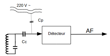
To make this 50 Hz noise disappear, several solutions are possible. The easiest way is to increase the coupling capacity Cc. If this capacitance is 100 nF, the 50 Hz voltage at the detector input will only be 2 µV. If the polarization of the detector stage allows it, for example for a FET, the easiest way is to remove the Cc capacitor. Another way is to shunt the coupling capacitor Cc with a resistor with the lowest possible value. In all cases, the 50 Hz impedance between the detector input and ground should be as low as possible.
6 Low frequency amplifier with low noise
It is often essential to attenuate the signal at the receiver input to obtain satisfactory selectivity and avoid synchronization. The signal at the receiver output is therefore extremely weak. It is therefore essential to use a large AF amplification with low background noise.
7 Conditions to be met to build a high-performance regenerative receiver
Finally, here are the conditions to be met for the design of a regenerative receiver.
- Use of a low L/C ratio (high tuning capacity, at least 470 pF for BPT). This improves frequency stability and reduces synchronization.
- Use of an adjustable RF attenuator at the receiver input. This reduces the risk of receiving powerful out-of-band stations.
- Use of a separator stage between the antenna attenuator and the regenerative stage. This is essential to avoid the risk of background noise appearing during oscillations (tunable hum) and to reduce frequency variations that occur when adjusting the RF attenuator.
- Shunt the diodes of the power supply circuit with 10 nF capacitors to eliminate the same noise.
- Provide a circuit with a low impedance at 50 Hz between the detector input and ground, for example by using a high capacity (100 nF). This eliminates the background noise induced by capacitive coupling with the 50 Hz mains.
- Use of a high gain, low noise AF amplifier to achieve a satisfactory output power.
Olivier ERNST
F5LVG
12-2019